
Extrusion System
The extrusion system of an FDM printer typically consists of a filament feeding mechanism, a heating unit, a nozzle, and a cooling fan.
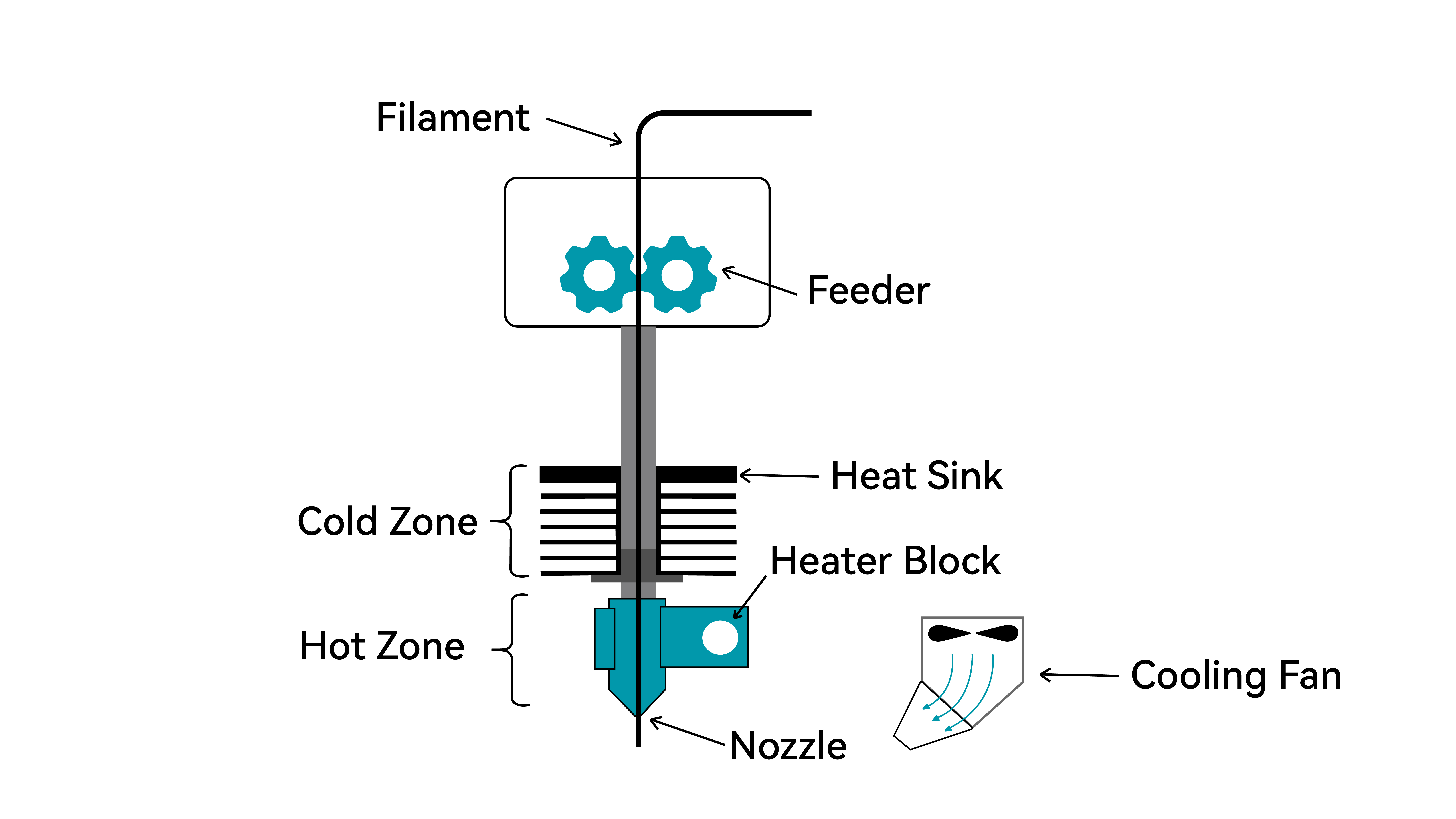
Filament Feeding Mechanism (Cold Zone)
Also known as the cold zone, the filament feeding mechanism is the driving force of the extrusion system. It is responsible for pushing solid filament into the hotend in a stable and controlled manner.
Typical components:
- Stepper motor: Provides precise rotational motion, enabling both forward (extrusion) and reverse (retraction) movement.
- Drive gear: Directly contacts the filament; its teeth grip the filament surface to generate pushing force.
- Idler gear (or idler wheel): Presses the filament from the opposite side to prevent slipping.
- Tension adjustment mechanism: Adjusts the pressure applied by the idler gear to accommodate different filament types and diameters.
Heating Unit (Hot Zone)
Also known as the hot zone, this component melts solid filament, making it pliable and allowing it to be extruded smoothly through the nozzle to effectively bond with adjacent layers.
Typical components:
- Heater block: Usually made of aluminum for good thermal conductivity and moderate heat capacity; houses the heater cartridge and temperature sensor
- Heater cartridge: A resistive heating element that generates heat when powered, raising the heater block to the target temperature
- Temperature sensor (thermistor): Monitors the temperature in real time and sends feedback to the control board for PID temperature regulation
- Heat break: Located between the heater block and heatsink, typically made of stainless steel or titanium to stop heat from moving upwards
Nozzle
The nozzle is where the molten material is extruded, determining the width and precision of the printed lines.
| Parameter | Typical Range | Description |
|---|---|---|
| Orifice diameter | 0.2mm – 0.8mm | 0.4 mm is the most common, balancing speed and detail |
| Material | Brass / Stainless steel / Hardened steel / Ruby-tipped | Brass is general-purpose; hardened steel is ideal for abrasive materials like carbon fiber or glass fiber |
| Structure | Integrated / Replaceable tip | Replaceable designs allow easier maintenance and swapping |
Hotend Cooling Fan
The hotend cooling fan is mounted on the heatsink (cold end side) and provides active cooling within the extrusion system. Its function is to continuously cool the heatsink, keeping the filament solid and rigid before it enters the hotend.
This prevents heat from creeping upward into the feeding mechanism, which could otherwise soften or deform the filament prematurely. The hotend fan typically runs at full speed whenever the printer is powered on and should not be turned off.
Working Principle:
Heat from the heater block naturally moves upward through its metal components. The heatsink, with its large surface area, works together with the cooling fan to dissipate this heat and to maintain a lower temperature.
As a result, the filament remains solid while passing through the heatsink region and only begins to melt once it reaches the heater block.
Common Issues:
Hotend fan failure → Heat creep causes the filament to soften prematurely, leading to clogs (often observed as extrusion stopping mid-print)
Insufficient fan speed → Inadequate cooling can also result in clogging due to poor heat dissipation
Extruder Types
The extruder is a core component of an FDM 3D printer, responsible for feeding solid filament into the hotend in a stable and controlled manner. Based on the mounting configuration, extruders are typically divided into two types:
| Direct-Drive Extruder | Bowden Extruder |
|---|---|
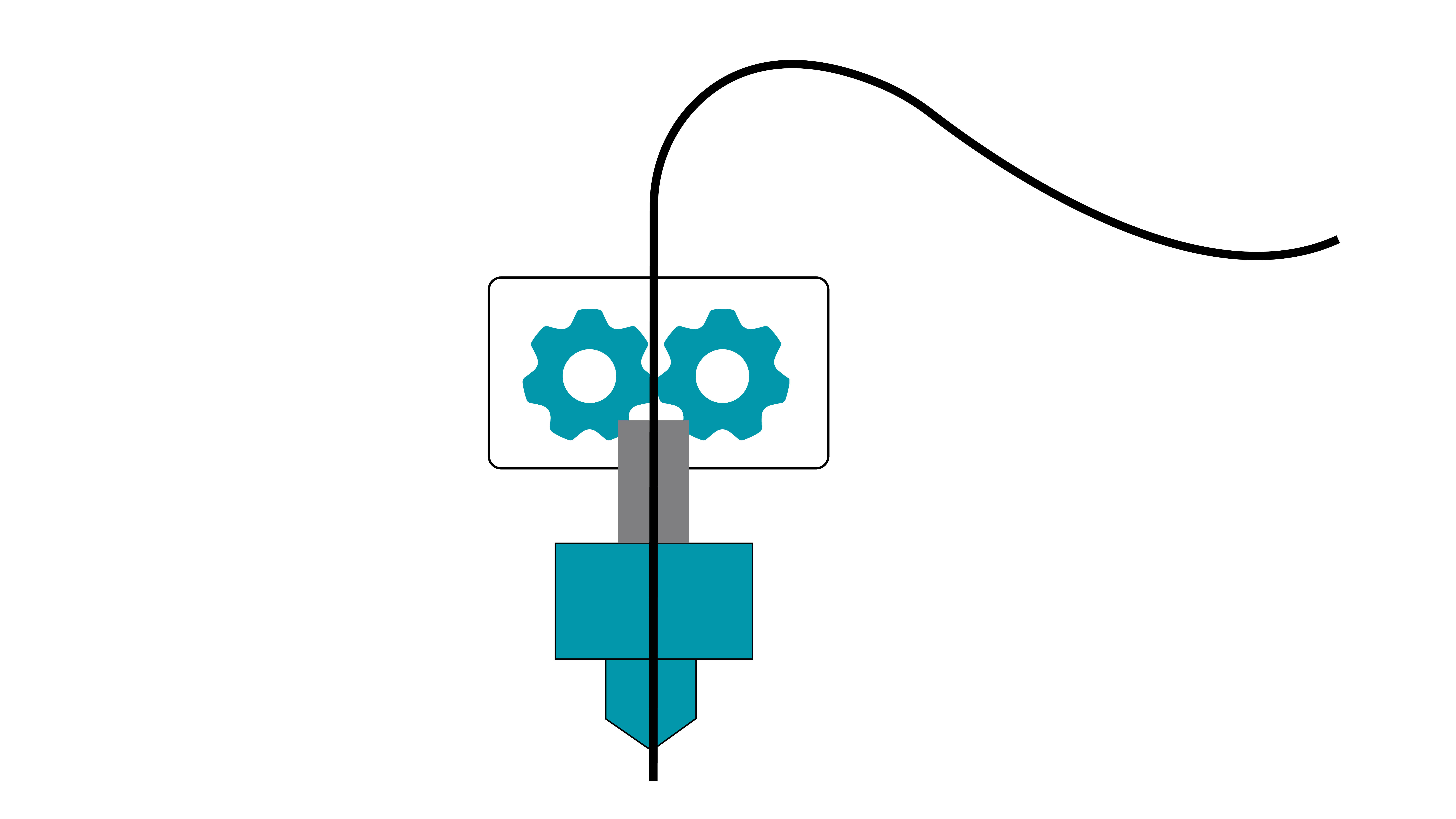 | 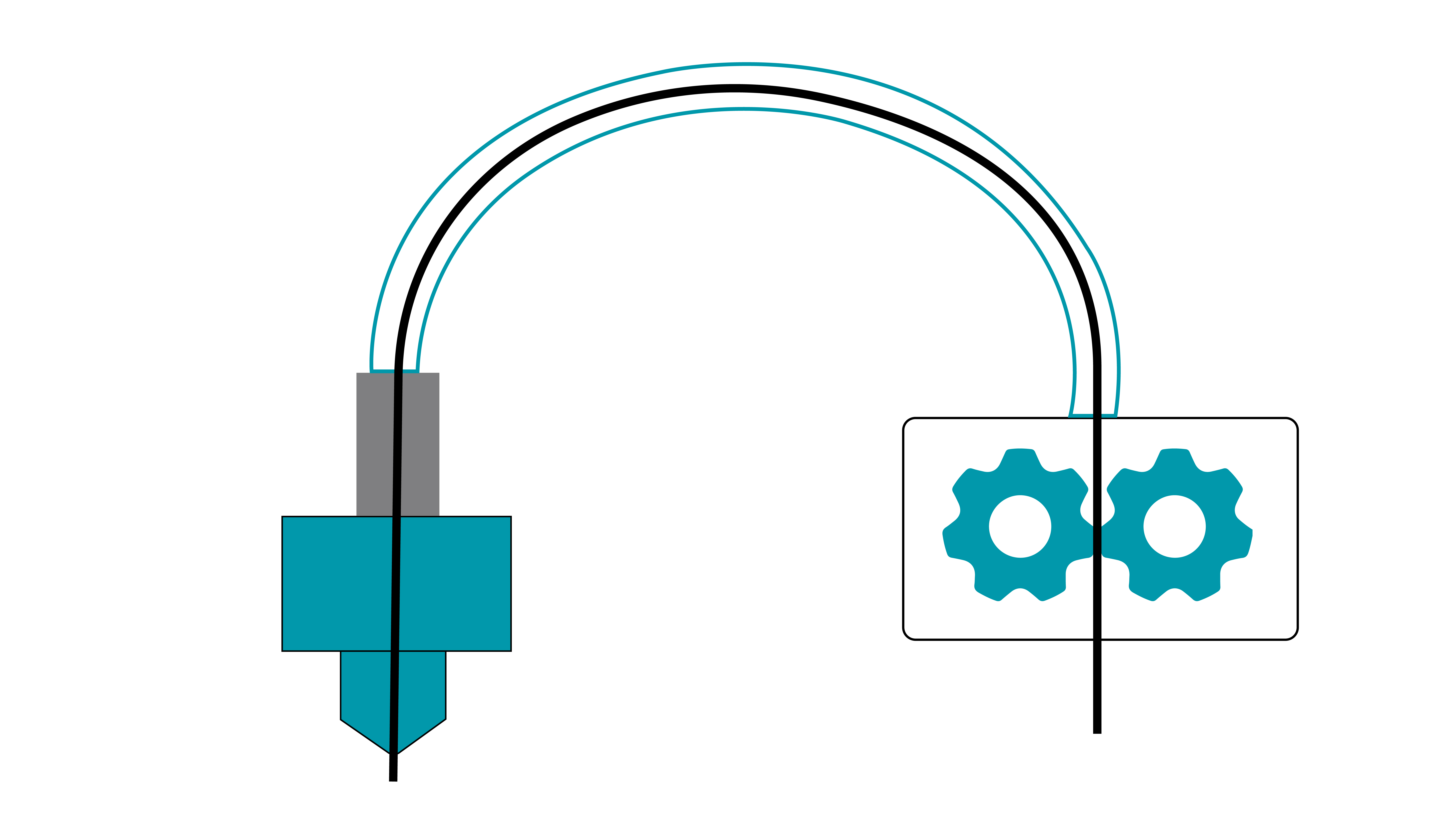 |
Direct-Drive Extruder
In a direct drive extruder, the stepper motor and filament feeding mechanism are mounted directly on the print head, forming a rigid connection with the nozzle.
Key Characteristics
| Aspect | Description |
|---|---|
| Extrusion response | Very fast (short filament path, immediate retraction response) |
| Flexible materials | Excellent (soft filaments like TPU are less likely to buckle or jam) |
| Print head weight | Heavier (includes the motor) |
| Print speed | Limited (higher inertia) |
| Retraction performance | Strong (reduced stringing) |
Typical Applications
- Printing flexible materials (TPU, TPE)
- Models requiring precise retraction control
- Low to medium-speed printing
Bowden Extruder
In a Bowden extruder, the stepper motor and feeding mechanism are mounted on the printer frame, away from the print head. Filament is guided through a long PTFE tube into the hotend.
Key Characteristics
| Aspect | Description |
|---|---|
| Extrusion response | Slower (elastic lag due to the long filament path) |
| Flexible materials | Limited (TPU may bend or jam inside the tube) |
| Print head weight | Lightweight (motor is not mounted on the print head) |
| Print speed | Higher (reduced moving mass) |
| Retraction performance | Moderate (requires longer retraction distances) |
Typical Applications
- High-speed printing (>150 mm/s)
- Large-format printers (reduced moving mass improves stability)
- Printing rigid materials (PLA, ABS, PETG, nylon, etc.)
Motion System Types
The motion system of a 3D printer determines how the print head (or build platform) moves along the X, Y, and Z axes. Different motion system designs directly affect print accuracy, speed, machine size, and overall stability.
Based on movement architecture, common FDM 3D printer motion systems can be classified into the following types:
Cartesian (XYZ) Motion Systems
Moving Build Platform (Z-axis)
After each layer is printed in the XY plane, the build platform moves downward along the Z-axis by one layer height. The print head continues printing subsequent layers while operating within a relatively fixed height range.
Advantages:
- Simple structure
- Easy to calibrate
- Low cost
- Stable printing process
Limitations:
- Limited print speed
- Requires additional depth for bed movement (front/back)
- Z-axis height depends on lead screw length, increasing machine height significantly
Typical applications: Widely used in desktop FDM printers
Fixed Build Platform
In this design, the print head moves along the X and Z axes, while the build platform (or gantry system) moves along the Y-axis. Since the platform does not move vertically, the structure can be more rigid.
Advantages:
- Stable platform (reduced model vibration)
- Z-axis motion handled by the print head (supports dual lead screws or gantry systems)
- Easier to scale build volume, especially in the XY plane
Limitations:
- requires more space
- Heavier print head
- More complex calibration compared to moving-bed designs
Typical applications:
- Industrial additive manufacturing systems
- Large-format FGF or concrete printing equipment
Infinite Z-axis (Belt Printers)
This design uses a conveyor belt as the build surface. After each layer is printed, the belt moves forward, carrying the printed part with it, while new layers are printed at the rear.
Advantages:
- Enables virtually unlimited print length
- Suitable for continuous or batch production
Limitations:
- Smaller effective XY build area
- More complex setup and calibration
- Requires specialized slicing software
Typical applications:
- Printing long parts
- Batch production workflows
Delta Motion System
Also known as a Delta or parallel arm system, this design suspends the print head at the intersection of three independently driven arms. Movement in X, Y, and Z directions is achieved by coordinated changes in arm positions.
Advantages:
- High printing speed
- Efficient Z-axis movement
- Good build volume utilization for cylindrical or symmetric models
Limitations:
- Lower accuracy for large prints
- Non-linear kinematics require complex motion calculations
Typical applications: Desktop additive manufacturing systems
Polar Motion System
Polar motion systems use a polar coordinate system to define print head position. Positioning is achieved through a combination of a rotating build platform and linear radial movement.
Unlike Cartesian systems, where each axis moves independently in straight lines, the build platform rotates while the print head moves along a single radial axis. Together, they cover the entire build area.
Advantages:
- High precision with relatively simple mechanical structure
- Reduced X/Y movement complexity
- Potential improvements in speed and stability
Limitations:
- Requires specialized slicing software to generate polar-coordinate toolpaths
- Higher implementation complexity and cost
Typical applications:
- Industrial additive manufacturing
- Ideal for circular or symmetric parts (e.g., gears, bearings)
Robotic Arm Systems
These systems use multi-axis robotic arms as the printing mechanism. The print head is mounted at the end effector, and positioning is achieved through coordinated joint movement.
Advantages:
- Highly flexible movement
- Capable of printing at various angles and orientations
- Suitable for complex geometries
- Broad material and process compatibility
Limitations:
- High cost
- Complex control systems
- Not compatible with standard slicing software
- Motion range limited by joint constraints, requiring careful path planning
Nozzle
The nozzle is a small but critical component of an FDM 3D printer, typically attached to the hotend. During printing, filament is pushed into the hotend, melted in the heater block, and extruded through the nozzle to form layers on the build plate. The nozzle directly affects print accuracy, speed, and overall quality.
Common Materials
| Material | Characteristics | Suitable Materials | Notes |
|---|---|---|---|
| Brass | Most common, excellent thermal conductivity, low cost | PLA, ABS, PETG, Nylon | Wears quickly; not suitable for abrasive filaments (e.g., carbon fiber, glow, wood-filled) |
| Stainless Steel | Corrosion-resistant, food-safe options available | Corrosion-resistant, food-safe options available | Lower thermal conductivity than brass |
| Hardened Steel | Extremely wear-resistant | Carbon fiber, glass fiber, metal-filled, glow filaments | Lower thermal conductivity; may require higher temperatures |
| Copper / Copper Alloys | Excellent heat transfer, even heating | High-speed printing, high-temp plastics (e.g., PC, PEEK) | Higher cost; prone to oxidation |
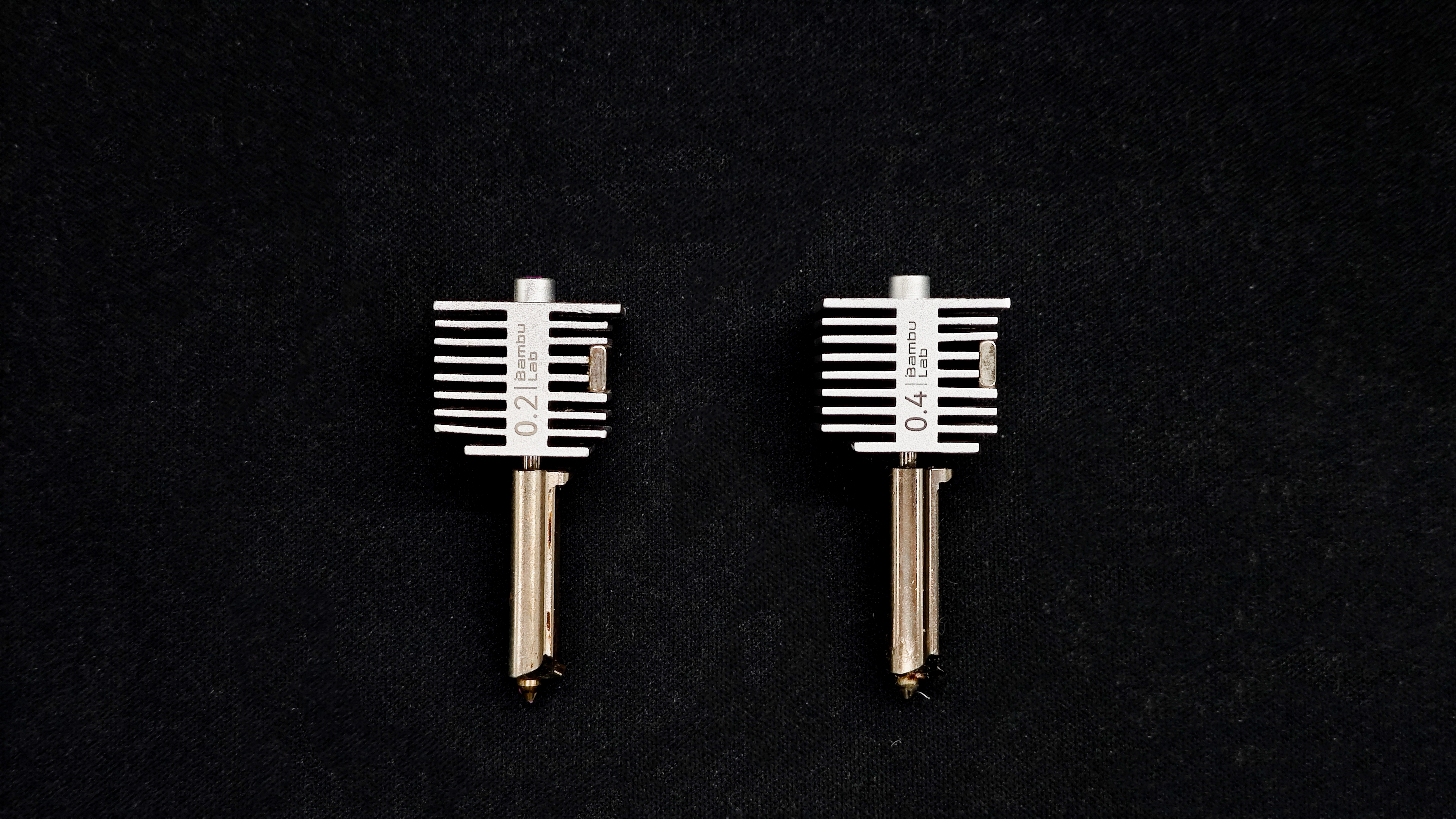
Nozzle Size
Nozzle size refers to the extrusion hole diameter. Different sizes suit different needs. For desktop FDM printers, 0.4 mm is the standard. A typical set (0.2 / 0.4 / 0.6 / 0.8 mm) covers most use cases.
| Diameter | Characteristics | Typical Use |
|---|---|---|
| 0.2 mm | High detail, very slow, prone to clogging | Miniatures, figurines, jewelry, small parts |
| 0.4 mm | Balanced performance, most common | General-purpose printing |
| 0.6 mm | Faster printing, reduced detail | Functional parts, containers, batch printing |
| 0.8 mm | Very fast, visible layer lines | Large models, vases, rough prints |
How to Prevent Nozzle Clogging?
- Use high-quality filament with tight diameter tolerances
- Keep filament clean: dust can carbonize inside the nozzle and cause clogs
- Avoid moisture: wet filament can create bubbles and unstable extrusion
- Print within recommended temperatures and use proper retraction settings
Note: Small nozzles (e.g., 0.2 mm) are much more prone to clogging. Regular cleaning and proper filament storage are essential.
How to Clear a Clogged Nozzle?
Choose a method based on severity:
Mild Clog
Symptoms: thin or inconsistent extrusion
Method: Cold Pull
1. Heat nozzle slightly above printing temperature (e.g., ~220°C for PLA)
2. Manually extrude filament until flow appears
3. Cool down to ~70°C
4. Retract and pull filament out
5. Cut off dirty tip and repeat 2–3 times
Moderate Clog
Symptoms: little to no extrusion, extruder slipping
Method: Cleaning Needle
1. Heat nozzle above printing temperature
2. Use a 0.2–0.35 mm needle to clear the nozzle from below
3. Repeat and test extrusion
4. Combine with cold pull if needed
Severe Clog
Symptoms: complete blockage, cannot be cleared
Solution: Replace the nozzle
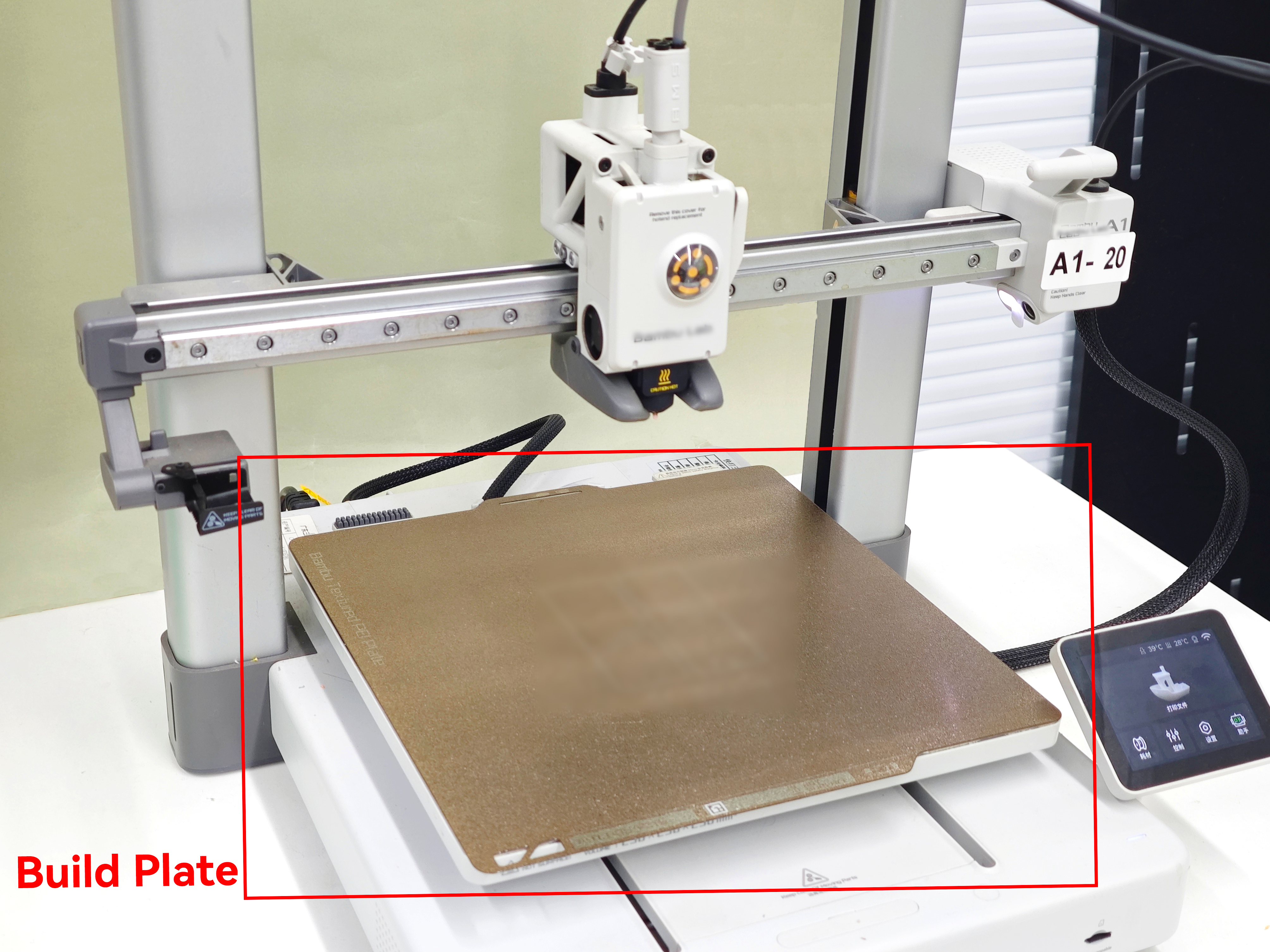
Build Plate
The build plate (also known as the print bed) is the surface on which a 3D printer creates objects layer by layer. It plays a critical role in print quality, first-layer adhesion, and overall print success.
Functions of the Build Plate
- Supports the first layer: Essential for achieving a successful first layer.
- Maintains positional accuracy: Keeps the model fixed in place during printing.
- Affects surface finish: The texture and material of the plate influence the appearance of the bottom surface.
- Temperature control (for heated beds): Maintains a stable temperature to reduce warping.
Types of Build Plates
Non-Heated Build Plate
A basic platform without temperature control, typically used for easy-to-print materials such as PLA.
- Simple structure, Lower cost
- Limited material compatibility
- Higher risk of poor adhesion with engineering materials
Heated Build Plate
A platform equipped with heating elements to maintain a controlled temperature.
- Improves adhesion and reduces warping
- Essential for materials like ABS, PETG, and Nylon
- Standard on most modern FDM 3D printers
Common Build Surface Materials
Glass Plate
A rigid, non-metallic surface with a smooth and flat finish. It can produce a glossy, mirror-like bottom surface on prints. Glass itself does not generate heat and is typically placed on top of a heated aluminum bed or paired with a heating element underneath. It is usually secured with clips.
Pros:
- Smooth and flat surface for high-quality bottom finishes
- Easy to clean
- Scratch-resistant and durable
Cons:
- Slow heat transfer and longer preheating time
- Not flexible; requires a scraper for part removal
Compatible Materials:
PLA can be printed directly on top of a glass plate. For PETG, ABS, Nylon, and similar materials, it is recommended to apply glue (glue stick or spray) or use masking tape.
Rigid Metal Plate (Aluminum / Stainless Steel)
Rigid metal plates are commonly used as the base of heated beds. Aluminum plates are widely used due to their excellent thermal conductivity, but bare metal surfaces provide poor adhesion and typically require additional surface treatments such as PEI sheets or adhesives.
Pros:
- Excellent thermal conductivity
- Good flatness control
Cons:
- Very poor adhesion when used bare
- Aluminum plates are not magnetic and require clips; stainless steel plates can be magnetic but are heavier
Compatible Materials:
When used on their own, most materials require glue or tape. With surface coatings applied, compatibility depends on the coating material.
Spring Steel Sheet (Flexible Build Plate)
A spring steel sheet is a flexible, magnetic build plate base. It attaches to the heated bed via a magnetic layer underneath. Its key advantage is easy part removal—prints can be detached simply by bending the plate, eliminating the need for a scraper.
Spring steel sheets themselves do not provide sufficient adhesion and must be used with surface coatings. In practice, they are commonly used as a composite system (spring steel + coating). Coating names such as PEO or PEX may vary by manufacturer and are not strictly standardized.
Pros:
- Removable and flexible for easy print removal
- Magnetic attachment for convenient installation
Cons:
- Coatings are consumable and may wear over time
Common Coating Types for Spring Steel Sheets:
1. Textured PEI Coating
A powder-coated textured PEI (Polyetherimide) surface with a fine granular finish. It provides reliable adhesion for a wide range of materials without additional adhesives in most cases. Prints typically release automatically after cooling.
Compatible Materials:
PLA, TPU, PETG can be printed directly on a PEI sheet. For high-temperature materials such as ABS, ASA, PA, and PC, applying a thin layer of glue is recommended.
2. Smooth PEI Coating
A smooth PEI film that provides strong adhesion and a glossy bottom surface finish.
Compatible Materials:
PLA, ABS, and ASA can be printed directly on a smooth PEI sheet. PETG is strongly recommended to use with a release agent or switch to textured PEI. TPU can be printed directly but may adhere too strongly.
3. PEO Coating
A functional coating (commonly referred to as PEO, though definitions vary by manufacturer) designed to balance adhesion and release, especially for materials like PETG.
Compatible Materials:
PETG and TPU typically do not require additional adhesives. Adhesion for PLA may be weaker depending on the product.
4. PEX Coating
An engineering-grade coating (commonly referred to as PEX) focused on high-temperature resistance and wear durability, suitable for demanding applications.
Compatible Materials:
PETG, ABS, ASA, and other high-temperature materials. Performance depends on the specific formulation.
5. PP Coating
A specialized coating designed specifically for polypropylene (PP), addressing its notoriously poor adhesion.
Compatible Materials:
PP and PP-based composites. Adhesion to PLA and PETG is generally poor.
6. Nylon (PA) Coating
Designed to improve adhesion stability for nylon materials while reducing warping and edge lifting.
Compatible Materials:
PA (e.g., PA6, PA12), as well as reinforced nylons such as PA-CF and PA-GF.
7. BuildTak-like Surface Sheets
BuildTak-style sheets are adhesive-backed functional films made from heat-resistant polymers with micro-textured surfaces to enhance first-layer adhesion.
Compatible Materials:
Suitable for PLA, ABS, and PETG. TPU may adhere too strongly.
Printer Enclosure
A printer enclosure refers to an enclosed chamber added to a 3D printer to maintain a stable internal temperature environment. It is an essential measure when printing engineering materials such as ABS and Nylon, helping to prevent warping and layer separation.
Core Principle: Temperature Control and Thermal Shrinkage
FDM printing works by heating material to a molten state, extruding it, and then allowing it to cool and solidify. The success of a print largely depends on how evenly the material cools.
In an open environment, the model is exposed to ambient air and loses heat through a combination of cooling fans present on the printer and natural convection. In contrast, an enclosed environment surrounds the printer with materials such as acrylic, polycarbonate panels, or metal housing, allowing heat from the nozzle and heated bed to build up inside the chamber. This creates a relatively stable temperature and isolates the print from external airflow and temperature fluctuations.
Why can Printing Without an Enclosure cause prints to Fail?
Engineering materials such as ABS have a relatively high glass transition temperature (around 105°C) and a high thermal expansion coefficient. When printed in an open environment, they cool too quickly after extrusion, leading to significant thermal shrinkage.
This often results in two common defects:
1. Warping: The bottom layers shrink, causing edges to lift and detach from the build plate.
2. Layer separation (delamination): Upper layers contract and pull against lower layers, causing cracks between layers.
An enclosure works by slowing down the cooling process, allowing the material to solidify more gradually—similar to an annealing effect—thereby reducing internal stress.
Material Guidelines for Enclosure Use
| Material Category | Typical Materials | Enclosure Recommendation | Explanation |
|---|---|---|---|
| Basic Materials | PLA, PVA | Not required | PLA has a low melting point and minimal shrinkage. In an enclosed high-temperature environment, it may become too soft, leading to poor cooling, heat creep, or even nozzle clogging. |
| Engineering Materials | ABS, ASA, PC, Nylon (PA) | Strongly recommended | These materials have high shrinkage rates. Without an enclosure, warping and cracking are very likely. For ABS and ASA, enclosure also helps contain potentially harmful fumes for filtration or ventilation. |
| Special Materials | PETG, TPU (Flexible) | Depends on conditions | PETG has low shrinkage and usually does not require an enclosure, though a draft shield can help for large prints. TPU benefits from faster cooling, and high enclosure temperatures may cause extrusion instability, so open printing is recommended. |
Open printing is suitable for ease of use, low cost, and common materials like PLA and PETG. In contrast, using an enclosure is essential for producing high-strength, heat-resistant, and warp-free parts with engineering materials
If you primarily print with PLA, an open or partially open setup is sufficient. However, if you plan to print functional parts using ABS or Nylon, a printer with an actively temperature-controlled enclosure is strongly recommended.