

Digital Modeling Phase
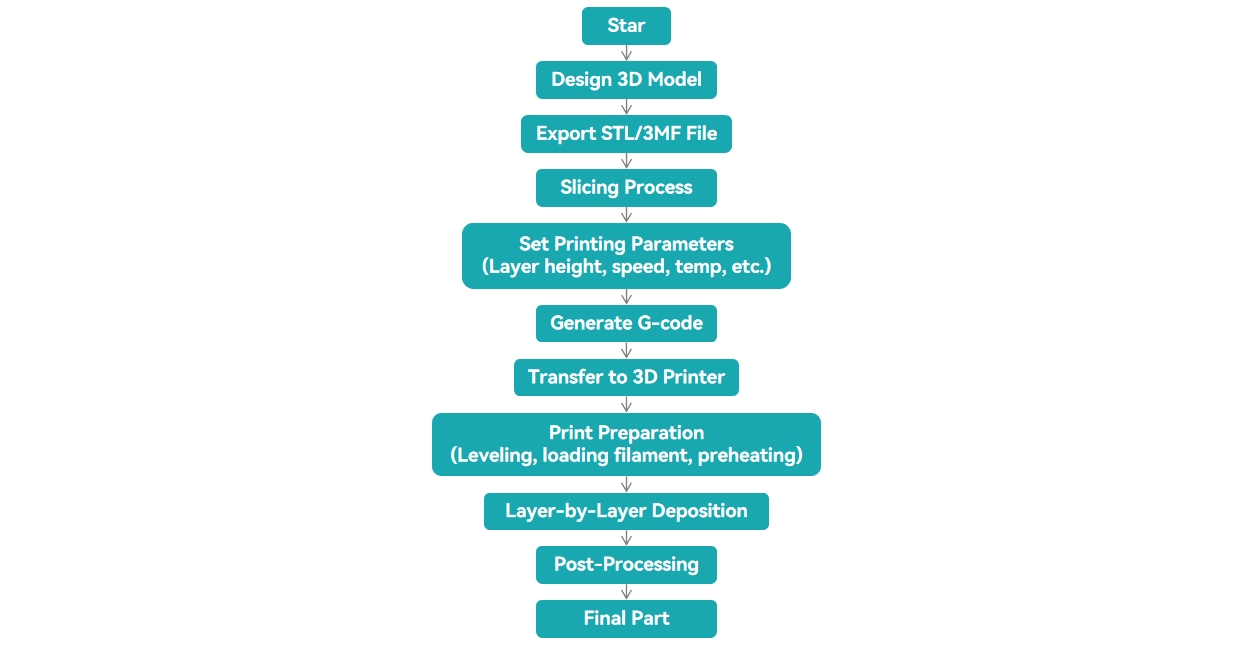
In the additive manufacturing workflow, the process begins with creating a 3D digital model using computer-aided design (CAD) software such as AutoCAD or SolidWorks.
This model fully defines the geometry and dimensional parameters of the planned part to print and is typically exported into industry-standard file formats such as STL or 3MF.
※ CAD is the use of computer software to create and edit digital designs, including 2D drawings and 3D models. It is widely used in engineering and product design, and in 3D printing it serves as the starting point for creating printable models.
| Format | STL | OBJ | PLY | STEP | IGES | AMF | 3MF |
| Data Model | Mesh | Mesh + Texture | Point / Mesh | B-Rep | Surface | XML Mesh | XML Manufacturing |
| Geometry Representation | Triangular mesh | Triangular mesh + texture map | Point cloud + polygon | NURBS / Solid | NURBS surface | Triangular mesh + semantics | Triangular mesh + process info |
| Data Structure | Simple (vertices + normals only) | Text (.obj + .mtl) | Text / Binary | EXPRESS (engineering model) | Text-based structure | XML | XML (zipped structure) |
| Geometric Accuracy | ★★★ | ★★★ | ★★★★ | ★★★★★ | ★★★★ | ★★★★ | ★★★★★ |
| Material Info | ❌ | ⚠(MTL) | ❌ | ✅ | ⚠ | ✅ | ✅ |
| Color Support | ❌ | ✅ | ✅ | ❌ | ❌ | ✅ | ✅ |
| Directly Printable | ✅ | ✅ | ✅ | ❌ | ❌ | ✅ | ✅ |
| Primary Use | Rapid 3D printing | Visualization & rendering | 3D scanning | Engineering design | CAD data exchange | Multi-material printing | Industrial manufacturing standard |
| Typical Scenarios | Prototype validation / FDM printing | Rendering / Product appearance design | Point cloud data / Reverse engineering | CAD modeling / Product development | Legacy system compatibility | Research / Advanced manufacturing | Automated production / Multi-material printing |
Slicing Phase
Slicing software (such as Cura or PrusaSlicer) converts the 3D model into layers along the Z-axis based on a predefined layer height.
During this process, the model is divided into a series of 2D cross-sectional layers, and toolpaths are generated for each layer. For every slice, the software calculates the outer perimeters, internal infill paths, and any required support structures. The final result is a machine-readable instruction file (typically G-code) that directs the printer’s movement and material deposition.
Fabrication Phase
In the fabrication phase, the printer constructs the physical object by depositing material layer by layer according to the generated toolpaths.
Taking Fused Deposition Modeling (FDM) as an example: Thermoplastic materials such as PLA, ABS, and PETG are heated in the hotend until they reach a molten state, then extruded through a nozzle at a controlled flow rate and deposited precisely along predefined paths, building the part layer by layer.
Bonding of the layers occurs through thermal diffusion and molecular chain entanglement. The resulting strength between layers is influenced by:
- Interlayer temperature
- Extrusion rate
- Cooling rate
Post-Processing Phase
After printing, post-processing is often required to achieve the desired mechanical properties or surface finish:
- Support removal
- Surface finishing (e.g., sanding, bead blasting)
- Annealing (to improve crystallinity and mechanical strength)
- Post-curing (for resin-based printing processes)